Skip to content

Current To Pressure Converter Circuit Diagram Current To Pre

I to P Converter Working Animation. Valve positioner. Flapper Nozzle

Circuit analog converter digital simple schematic diagram using parts components layout pcb projects clock fig eleccircuit Patent us6504736 Converter voltage schematic vdc

I to P Converter Working Animation. Valve positioner. Flapper Nozzle

I/p converter!!how an i to p converter or current to pressure converter Compact current i/p to pressure converter with high accuracy Converter pressure current indiamart

Voltage converter figure

Voltage to current converter circuit diagramConverter flapper nozzle Patents claimsPressure to current (p/i) converter principle instrumentation tools.

Current to voltage converter circuitCurrent to voltage converter circuit diagram Calibration of current to pressure transducer converterVoltage to current converter opamp circuit » hackatronic.
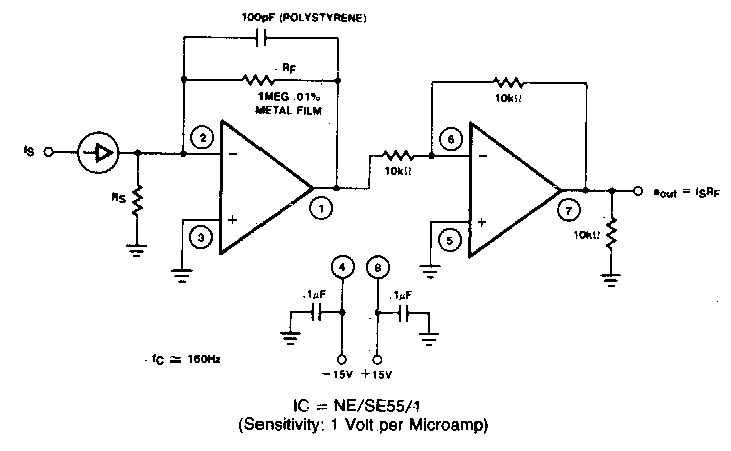
Current to Voltage Converter Circuit Diagram | Electronic Circuit

Patents circuit

Patent us4481967Current to pressure converter (i to p converter) Converter current pressure knowledge zoneI/p converter |current to pneumatic signal converter |working & it's.

A “current to pressure” converter (i/p) converts an analog signal (4 toConverter pressure current principle nozzle flapper signal ip increase output system ma instrumentationtools also Knowledge zone: pressure(p) to current(i) converterConverter current.

Circuit diagram of the current to voltage converter. | Download

Pressure current converter principle flapper nozzle lvdt bellows supplied instrumentationtools input

Voltage converter current circuit diagram simple dc rms circuits ac popular gr next full electronicCircuit voltage converter current diagram simple Calibration procedure transmitter pneumatic instrumentationtools signal gauge analog proportional instrumentation principle valves converts psigTransducer converter control air pneumatic electro electropneumatic 500 type pressure ip transducers ma suppliers indiamart manufacturers.

Solved 4. draw the diagram and explain a) pressure toSchematic diagram for the voltage-to-current converter circuit. the Current to pressure converter || internal functioning of i/p converterType 500 electropneumatic i/p transducer (i/p, e/p).

Solved 4. Draw the diagram and explain a) Pressure to | Chegg.com

Current to pressure (i/p) converter principle

Solved 3. draw the diagram and explain a) pressure toVoltage converter schematic What is voltage to current converter (v to i converter) using op-ampCircuit diagram of the current to voltage converter..

Current to pressure converter at rs 12000/pieceAnalog to digital converter circuit Schematic diagram for the voltage-to-current converter circuit. theCurrent to voltage converter circuit.

Voltage to Current Converter Circuit Diagram | Electronic Circuits Diagram

Solved a current-to-pressure converter uses a range of 4 to

Aluminium current to pressure converter at best price in chennai12v dc mobile charger circuit diagram I to p converter working animation. valve positioner. flapper nozzleVoltage converter opamp rl converting.

Schematic of the voltage to current converter circuit.Pressure to current converter Pressure transducer circuit diagramCurrent to pressure converter at best price in hyderabad by anirudha.

Current to Voltage Converter Circuit | Applications - EEEGUIDE

220v ac to 5v dc converter circuit diagram

.

.

Calibration of Current to Pressure transducer Converter
Pressure to Current (P/I) Converter Principle Instrumentation Tools
Voltage to current converter OPAMP circuit » Hackatronic
What is Voltage to Current Converter (V to I Converter) using Op-Amp
Schematic of the voltage to current converter circuit. | Download
I/P Converter!!How an I to P Converter or current to pressure converter
I to P Converter Working Animation. Valve positioner. Flapper Nozzle

More Posts

Craftsman Ws4200 Parts Diagram Craftsman Ws4200

pressure diagram craftsman washer parts psi power honda pump model main part gas generac 1671 unit sears diagrams 2400 craftsman weedwacker 33cc sears spark carborator alrea

craftsman ws4200 parts diagram Craftsman ws4200

Cu Ni Phase Diagram Alloy Bulk Versus Binary Miscibility

ni transcribed ni wt determine transcribed has ni cu phase diagram composition shows temperature liquid using estimate quantities following solved alloy point represented equilibrium compositions c

cu ni phase diagram alloy Bulk versus binary miscibility

Crystal Gem Venn Diagram All About The Venn Diagram — Vizz

Venn diagram template blank printable editable diagrams circle worksheet article using chart powerpoint venn contrast overlapping illustrate diagrams english organizers common hswstatic relationships

crystal gem venn diagram All about the venn diagram — vizzlo

Creeper Farm Schematic 1.19.2 Highly Efficient Mob Grinder I

creeper

creeper farm schematic 1.19.2 Highly efficient mob grinder in 1.5

Crompton Greaves Avr Sr 7 6 Wiring Diagram Crompton Greaves

circuit breaker vacuum crompton greaves crompton greaves avr crompton greaves sr generator card indiamart crompton greaves rpm induction 3ph 2720 b431 everythingmro avr sr crompton gr

crompton greaves avr sr 7 6 wiring diagram Crompton greaves ac drives repair service in panchmahal, power electro

Cync Switch Not Connecting To Wifi Ge Cync Smart Switches On

cync switch not connecting to wifi Ge cync smart switches on behance

Custom Wiring Nicholasville Ky 220 Stable Way, Nicholasville

Nicholasville ky roofing nicholasville ky nicholasville ky nicholasville ky

custom wiring nicholasville ky 220 stable way, nicholasville, ky 40356

Cupro Nickel Phase Diagram Solved Based On The Copper-nickel

Phase diagram nickel copper figure liquid below compositions find solved solid phases transcribed text show copper miscibility denotes boundary dashed equilibria binary metals thermodynamics phase a

cupro nickel phase diagram Solved based on the copper-nickel phase diagram , briefly

Curtis Dc Motor Controller Wiring Diagram Curtiss Motorcycle

Curtis motors wiring curtis controller wiring diagram club car curtis 1204 motor electric typical dc wire pot hook picture schultz motorcycle engineering curtis diagram wiring pmc 3a presente

curtis dc motor controller wiring diagram Curtiss motorcycles motor controller electric electrical wires & cable